TOYOPUC-PCS-J
Safety control circuits made programmable by redundant logic circuits
Reduces the emergency stop response time by achieving high-speed response
Equipped with a security function to ensure safety
Fitted with a DIN rail for easy mounting
Improved maintainability through error history
1. Features of TOYOPUC-PCS-J
Japan’s first safety PLC As a company leading the way in safety control with TOYOPUC-PCS, JTEKT offers TOYOPUC-PCS-J, a compact safety PLC for which we have thoroughly pursued usability utilizing our proven experience.
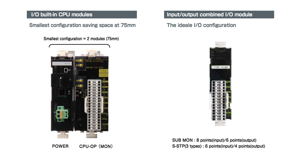
Realize down-sizing and user-friendliness
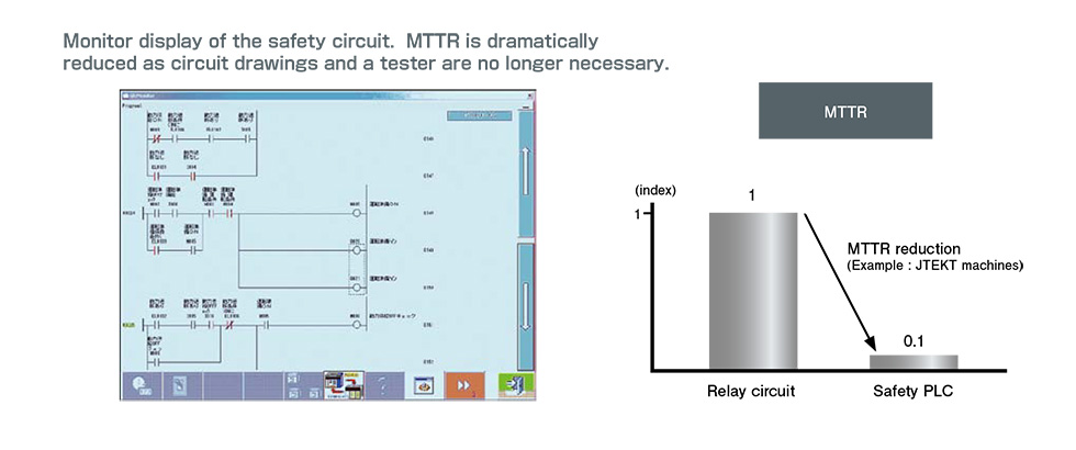
Visualization of safety circuits
Compact yet capable of achieving top level program capacity and rapid response time
| Item | TOYOPUC-PCS-J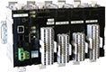 |
TOYOPUC-PCS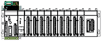 |
|
|---|---|---|---|
| Concept | Subject | Stand-alone safety system | Network safety system |
| Internal basic configuration | Software/hardware redundant configuration | ||
| Performance/ ・Spec |
Maximum response speed※ | 22.6ms | 17ms※1 |
| Program size | 16K words | 12K words | |
| I/O points | 256 point | 2048 point | |
- * semi-conductor output
- ※1 if smallest configuration
2. Safety-related conformed standards
| No. | Conformed standards. | Outline |
|---|---|---|
| 1 | IEC61508 | Functional safety of electrical/electronic/programmable electronic safety-related system |
| 2 | EN954-1 ISO13849-1 |
Safety of machinery - Safety-related parts of control systems Part 1: General principles for design |
| 3 | ISO13849-2 | Safety of machinery - Safety-related parts of control systems Part 2: Validation |
| 4 | NFPA79 | Electrical Standard for Industrial Machinery (NFPA: National Fire Protection Association) |
3. General specifications
| No. | Item | Test specifications | Specification | |||
|---|---|---|---|---|---|---|
| 1 | Power | Voltage: 24 VDC Current: Max 1A (Allowable range: 21.6-26.4 V DC) | ||||
| 2 | Power consumption | 24W | ||||
| 3 | Ambient temperature | 0~55°C | ||||
| 4 | Relative humidity | 30-85% RH (No condensation allowed) | ||||
| 5 | Atmosphere | No corrosive gas allowed | ||||
| 6 | Vibration resistance | IEC60068-2-6 | Frequency | Acceleration | Amplitude | No. of sweeps |
| 10~57Hz | - | 0.35mm | 20 times (1 octave/minute) |
|||
| 57~150Hz | 49m/s2 | - | ||||
| 7 | Shock resistance | IEC60068-2-27 | 147m/s23 times in X, Y and Z directions | |||
| 8 | Static electricity resistance | IEC-61000-4-2 | Gaseous discharge: ±8 kV Contact discharge: ±6 kV | |||
| 9 | Burst resistance (Fast transient test) |
IEC-61000-4-4 | Signal line: ±1 kv DC power line: ±1 kv Function ground line: ±1 kv |
|||
| 10 | Surge resistance | IEC-61000-4-5 | To ground: ±1 kv | |||
| 11 | Conducted interference of radio frequency electromagnetic field | IEC-61000-4-6 | 0.15~80MHz 10V 80% | |||
| 12 | Radiated, radio-frequency, electromagnetic field immunity | IEC-61000-4-3 | 80~2000MHz 10V/m 80% | |||
4. System component device list
4-1 CPU module (I/O built-in)
| Name | Type | Item | Specification | |||
|---|---|---|---|---|---|---|
| CPU-OP(MON) | TDC-6344 | CPU section | 1 | Program method | Stored program method | |
| Current consumption: 70 mA Mass: 260 g 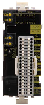 |
2 | Mass: 260 g | Cyclic operation method | |||
| 3 | Input/output control method | Image registration method | ||||
| 4 | Process speed | 15ms/15 ms/scan | ||||
| 5 | Program capacity | Source program size: max 16 kW (Executed program size: 64 KB) |
||||
| 6 | Hold memory | Program | Flash ROM | |||
| Safety data | No memory held | |||||
| 7 | Battery | Rechargeable (Lithium secondary battery: 5 years life) (Note) Only CPU-OP (MON) is attached |
||||
| 8 | Maximum connection slot number | 14 slots (including CPU-OP (MON)) | ||||
| 9 | No. of external I/O | 256point | ||||
| 10 | No. of internal outputs | 2048 points | ||||
| 11 | Display unit | 7-seg LED display Display contents switch between MOD SW and INC SW operations |
||||
| I/O section | 1 | Input/output format | Input | Photo coupler | ||
| Output | FET | |||||
| 2 | I/O points | Input | 2 points (+ common) 6point(-common) |
|||
| Output | 6point(-common) | |||||
| 3 | Voltage, current | Input | 24VDC 5mA/point | |||
| Output | 24VDC 0.5A/point | |||||
| 4 | Remarks | Double input 2 system (contact input × 2) Double output 2 system |
||||
4-2. I/O module
| No. | 1 | 2 | 3 | 4 | |
|---|---|---|---|---|---|
| Name | SUB MON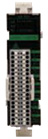 |
S-STP(E)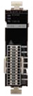 |
S-STP(LC)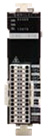 |
S-STP(E/LC)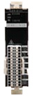 |
|
| Type | TDK-6340 | TDK-6346 | TDK-6347 | TDK-6348 | |
| Current consumption | 74mA | 68mA | 68mA | 68mA | |
| Input/output format | Input | Photo coupler | Photo coupler | Photo coupler | Photo coupler |
| Output | FET | FET | FET | FET | |
| I/O points | Input | 2 points (+ common) 6point(-common) |
2 points (+ common) 4point(-common) |
6point(-common) | 1point(+common) 5point(-common) |
| Output | 6point(-common) | 4point(-common) | 4point(-common) | 4point(-common) | |
| Voltage, current | Input | 24VDC,5mA/point | 24VDC,5mA/point | 24VDC,5mA/point | 24VDC,5mA/point |
| Output | 24VDC,0.5A/point | 24VDC,0.5A/point | 24VDC,0.5A/point | 24VDC,0.5A/point | |
| Mass | 200g | 185g | 185g | 185g | |
| Remarks | Double input 2 system (Double input 2 system) Double output 2 system |
Double input 2 system (Double input 2 system) Double output 2 system |
Double input 2 system (Light curtain input × 2) Double output 2 system |
Double input 2 system (Contact input × 1 Light curtain input × 1) Double output 2 system |
|
| No. | 5 | 6 | 7 | ||
| Name | S-IN(E)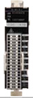 |
S-IN(LC)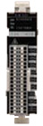 |
S-OUT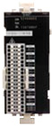 |
||
| Type | TDK-6356 | TDK-6357 | TDK-6358 | ||
| Current consumption | 62mA | 62mA | 74mA | ||
| Input/output format | Input | Photo coupler | Photo coupler | - | |
| Output | - | - | FET | ||
| I/O points | Input | 8point(+common) 8point(-common) |
16point(-common) | - | |
| Output | - | - | 16point(-common) | ||
| Voltage, current | Input | 24VDC,5mA/point | 24VDC,5mA/point | - | |
| Output | - | - | 24VDC,0.3A/point | ||
| Mass | 190g | 190g | 250g | ||
| Remarks | Double input 8 system (Contact input × 8) |
Double input 8 system (Light curtain input × 2) |
Double output 8 system | ||
4-3 Power source/base/parts
| No | Name | Type | Specification |
|---|---|---|---|
| 1 | Lithium battery | TIP-5426 | CPU-OP (MON) rechargeable battery (spare parts) |
| 2 | BASE |
TDR-6341 | Base for connecting modules |
| 3 | POWER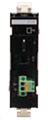 |
TDV-6338 | Power module Able to supply up to 9 modules including the CPU SN-I/F (Interface with the control PLC) USB connection (for a programmer connection) |
| 4 | BOOSTER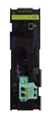 |
TDV-6339 | BOOSTER module When 10 or more TOYOPUC-PCS-J modules (including CPU modules) are used, set the BOOSTER module between slot 8 and slot 9 (count the CPU module as slot 0) to ensure stable power supply. |
4-4 Programming tool
| No | Name | Type | Specification |
|---|---|---|---|
| 1 | PCwin-Safe2 (Japanese) [CD-ROM] |
TJA-2071 | Programming software for TOYOPUC-PCS/PCS-J (PCwin-Safe, PCwin-Safe-J integrated environment software) [CD-ROM Japanese version] |
| 2 | PCwin-Safe2 (English)[CD-ROM] |
TJA-2073 | Programming software for TOYOPUC-PCS/PCS-J (PCwin-Safe, PCwin-Safe-J integrated environment software) [CD-ROM English version] |
| 3 | PCwin-Safe2 (Chinese)[CD-ROM] |
TJA-6314 | Programming software for TOYOPUC-PCS/PCS-J (PCwin-Safe, PCwin-Safe-J integrated environment software) [CD-ROM Chinese version] |
| 4 | PCwin-Safe2 (French)[CD-ROM] |
TJA-6287 | Programming software for TOYOPUC-PCS/PCS-J (PCwin-Safe, PCwin-Safe-J integrated environment software) [CD-ROM French version] |
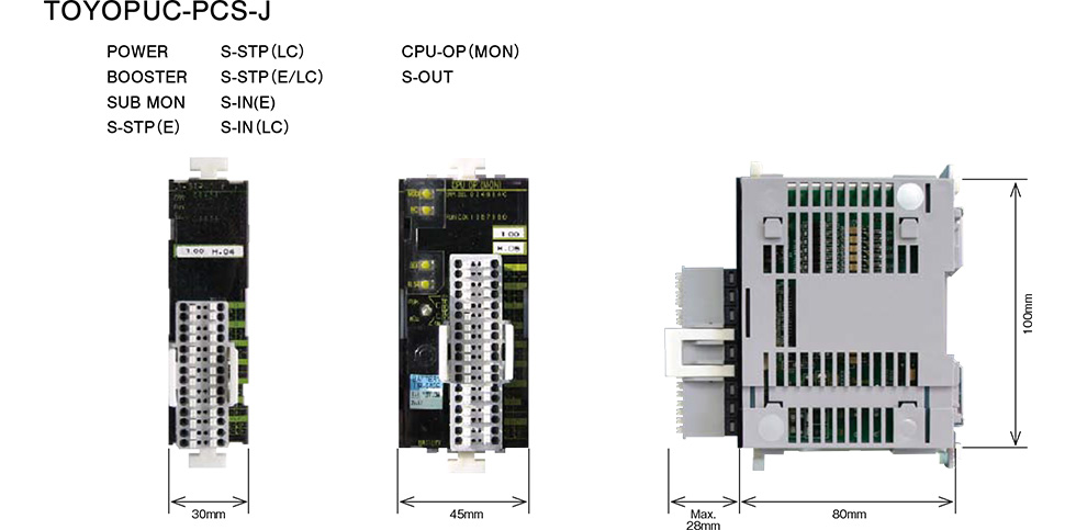
5.External dimensions